Drawing and purchase-order control
ASTM A513 tolerances
Tolerance depends on type, shape, size, wall, length, condition, and the characteristic being controlled. Use the official edition for normative limits.
On this page
The short answer
A513 tolerances are organized by manufacturing type, shape, and size range — there is no single tolerance for the specification. As-welded routes carry broader limits than drawn routes; squares and rectangles carry characteristics rounds do not (corner radii, squareness, twist). The normative limits are in the purchased standard, and producers may hold tighter negotiated limits than the standard requires.
The practical skill is not memorizing tables — it is identifying which characteristics your part actually needs controlled, then stating them so the producer can quote against reality.
Define the controlled characteristics
Identify outside dimension, inside dimension where applicable, wall, length, straightness, squareness, corner radii, twist, and end condition according to the product shape and part function.
For round tube destined for machining, the OD/ID relationship and wall concentricity usually dominate. For welded frames, straightness and twist usually dominate. Specify what the part cares about; accept standard limits for what it does not.
Resolve drawing conflicts
A blanket standard note can conflict with title-block or feature tolerances. Establish precedence and confirm exceptional requirements with the producer before order acceptance.
A drawing that states “ASTM A513 Type 5” and simultaneously dimensions the OD with a tighter title-block tolerance has created a conflict the receiving inspector will discover at the worst time. Decide which governs, and write it down.
Measurement matters
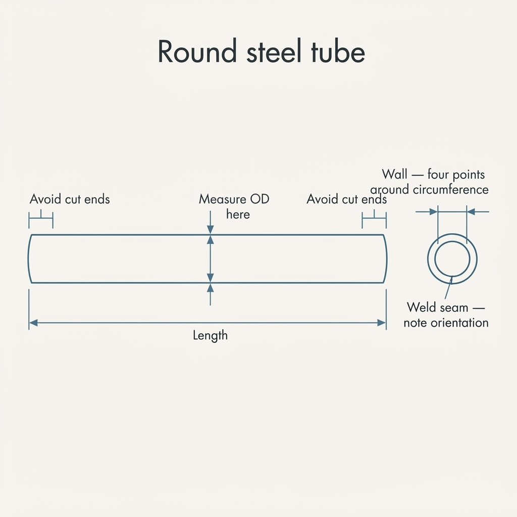
Agree on where and how characteristics are measured: distance from tube ends, orientation relative to the weld, ovality interpretation for rounds, and flat-to-flat versus corner measurements for shapes. Disagreements about method masquerade as disagreements about conformance.
The most common tolerance dispute we see is not about the product at all: the producer measured mid-length with a micrometer averaging across the weld, and the receiving inspector measured near a cut end with calipers at one orientation. Both read honestly; the numbers disagree. Method agreement before the first shipment prevents this entire category of rejection.
How A513 organizes tolerance thinking
Without reproducing controlled tables, the structure is worth understanding: tolerances in the standard scale with manufacturing type (as-welded routes carry broader limits than drawn routes), with size range (larger sections generally carry larger absolute limits), and with shape (rounds, squares, and rectangles each have their own characteristic set). Supplementary and negotiated requirements can tighten any of these where the producer agrees.
This structure is why copying a single tolerance number from a forum or a competitor's uncontrolled table is dangerous: the number may be real, but for a different type, size band, or edition than your order.
OD, ID, or wall: pick what governs
For a tube, outside diameter, inside diameter, and wall thickness are geometrically linked — a producer cannot hold all three to their tightest simultaneously. The standard's convention and industry practice is that the buyer identifies which dimensions govern and which float.
For machined parts that pilot on the OD, let OD and wall govern and accept the resulting ID. For parts that slide over a shaft or seal on the bore, consider ordering to ID and wall — a conversation DOM producers have daily. Stating all three with tight limits does not get you a better tube; it gets you a quote query, a price adder, or a silent producer decision about which one to ignore.
| Part function | Governing dimensions | Floating dimension | Practical implication |
|---|---|---|---|
| Machined on OD (pilots, press fits) | OD + wall | ID | Order to OD/wall; stock allowance on ID |
| Slides or seals on bore | ID + wall | OD | Discuss ID-governed ordering with a DOM producer |
| Welded frame member | OD + straightness | ID, wall (within standard) | Standard limits usually suffice |
| Formed or bent component | Wall + OD | ID | Wall consistency dominates bend quality |
Sources and limitations
- ASTM A513/A513M — Standard Specification for Electric-Resistance-Welded Carbon and Alloy Steel Mechanical Tubing — ASTM International. Controlling specification for types, tolerances, and ordering requirements. Purchase the current edition for all normative values.
These sources inform the qualitative guidance on this page. This publication does not reproduce their text, tables, numerical settings, or acceptance criteria. Normative requirements come only from the purchased current edition of the governing standard and your supplier agreement.