Manufacturing and process control
How ASTM A513 mechanical tubing is made
ASTM A513 mechanical tubing is not produced by one generic route. The order defines a manufacturing type, material, condition, shape, dimensions, tolerances, testing, certification, and other requirements. The mill then has to preserve that intent through strip preparation, forming, electric-resistance welding, cooling, sizing, inspection, and release.
This page explains the production logic. It does not reproduce controlled ASTM tables, establish acceptance criteria, or replace the official standard, drawing, supplier agreement, machine instructions, or qualified engineering judgment.
On this page
The process, stage by stage
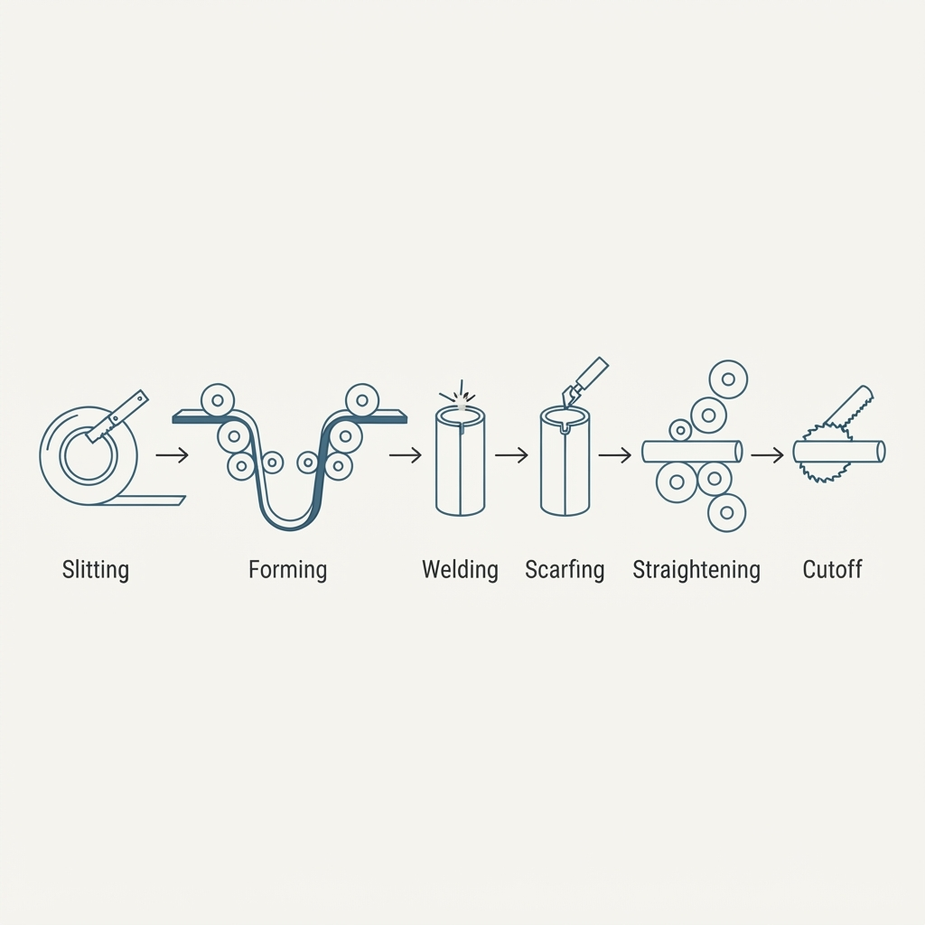
| Stage | Primary responsibility | Evidence worth preserving |
|---|---|---|
| Purchase definition | Communicate the required product and evidence | Standard edition, type, material/grade, condition, shape, dimensions, tolerances, tests, certification, end use |
| Coil and strip preparation | Supply consistent material with usable edges and identity | Supplier, heat/lot, chemistry or grade, actual thickness and width, camber, crown, burr orientation, edge condition |
| Entry | Present strip on the intended mill centerline | Entry position, guides, strip tracking, first-pass edge symmetry |
| Breakdown forming | Convert flat strip into a controlled open section | Exit geometry, strip gauge, pressure evidence, edge form, surface condition |
| Side passes | Support and steer the developing section | Pass position, stability, exit dimensions, metal-line relationship |
| Fin passes | Set the body, reduce girth, and prepare parallel edges | Outside perimeter or diameter after each pass, fin condition, edge presentation, reduction progression |
| ERW welding | Heat and forge prepared edges into a longitudinal seam | Power, line speed, pressure/upset, edge match, welded size, roundness, weld-test result |
| Cooling and scarfing | Remove external bead where required and stabilize temperature | Scarf condition, support, coolant condition, temperature stability |
| Sizing and reshape | Produce final dimensions and shape | Measurements after each driven stand, drive coordination, surface, straightness |
| Inspection and release | Confirm the ordered product and records | First-piece results, in-process checks, final inspection, test reports, certifications, deviation approvals |
The first stage at which a condition can be observed is often earlier than the point where the customer notices the defect. That is why progressive inspection is more useful than checking only finished tube.
Start with a complete order
A513 is an ordering specification. The mill cannot infer all required characteristics from a nominal size or from shorthand such as ERW, DOM, HREW, or CREW.
A complete order should resolve, as applicable:
- Standard and edition
- Manufacturing type
- Material or chemistry designation
- Condition
- Round, square, rectangular, or special shape
- Controlled dimensions and tolerances
- Length and quantity
- Surface and weld-bead expectations
- Testing and certification
- Supplementary requirements
- End-use constraints
- Priority when the PO, drawing, and specification appear to conflict
Use the A513 specification and RFQ builder on this site to assemble the description, then reconcile it against the official standard and supplier quotation before release.
Coil, slit edge, and entry condition
The forming process inherits variation from the coil. Two coils with the same nominal grade and thickness can behave differently because of actual thickness, hardness, yield behavior, crown, camber, residual stress, surface condition, or slit-edge quality.
Before setup conclusions are drawn, confirm:
- The material identity agrees with the production order
- Actual thickness and width are measured rather than assumed
- Slit burr, edge damage, and camber are within the plant's qualified range
- The strip is centered and guided without uncontrolled movement
- The first pass receives the strip at the intended height and centerline
A strip-tracking problem is not automatically a roll-contour problem. Entry movement, stand movement, unequal drag, worn components, and incorrect alignment can produce similar visible behavior.
Mechanical integrity before precision setup
A mill cannot hold alignment if its components move under load. Before changing roll settings to chase a product symptom, separate two questions:
- Is the relevant machine or tooling component mechanically sound?
- Is the sound component located at the correct centerline, pass line, orientation, and relationship to adjacent equipment?
The inspection scope normally includes foundations, hold-downs, stands, blocks, gibs, restraints, shafts, bearings, lead screws, keys, roll bores, spacers, guides, weld-box components, straighteners, and exit supports. Applicable OEM dimensions and bearing instructions control; vendor rules of thumb are not machine limits.
Breakdown forming
Breakdown passes begin the transformation from flat strip to an open tube. Their job is not simply to make the strip look round. They distribute bending work, establish edge form, preserve thickness, and deliver a stable incoming section to the fins.
Different tooling designs distribute that work differently. Common families include single-arc forming, modified-edge forming, reverse-bend or W-style forming, and combinations using multiple edge-forming passes. No family is universally best. Selection depends on material, diameter-to-thickness relationship, mill configuration, stand stiffness, gauge range, surface requirement, setup capability, and the work that should remain for the fin section.
More aggressive early edge forming can improve edge control and reduce later fin work, but it may also increase sensitivity to alignment, gauge, transition design, and setup. A forgiving design can tolerate more variation but may transfer work and wear downstream.
Useful breakdown evidence includes:
- Exit geometry from every driven pass
- Equality of inboard and outboard conditions
- Evidence that forming pressure has not unintentionally reduced strip gauge
- Contact or witness patterns
- Surface pickup or marking
- Strip tracking
- The condition presented to the first fin
Fin-pass preparation
The fin section progressively closes and confines the open tube. Its responsibilities include:
- Reducing the remaining girth in a controlled progression
- Setting the tube body
- Conditioning the strip edges
- Presenting matched, substantially parallel edges
- Leaving the intended allowance for the welding operation
Fin blades, roll contours, edge condition, incoming section, roll position, and reduction strategy work as a system. A damaged fin blade, excessive incoming girth, poor edge form, unequal pass setting, or speed mismatch may show up as marking, edge shavings, poor edge presentation, or an unstable weld.
Measure the product after each relevant pass. A final welded-size measurement cannot identify which fin first departed from the intended progression.
ERW seam formation
In electric-resistance welding, prepared strip edges are heated and forged together without filler metal. The process must coordinate:
- Edge position and match
- Heat input
- Line speed
- Forging pressure or upset
- Weld-roll condition and geometry
- Seam location
- Scarfing and support
- Material response
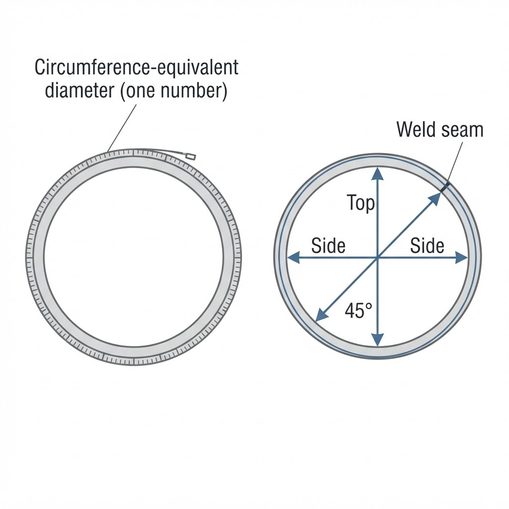
The weld box should receive a stable, correctly prepared open tube. It should not be expected to repair an incorrect strip width, damaged edge, unstable fin section, or gross misalignment.
Circumference-equivalent diameter alone does not prove the welded tube is round. Measure multiple axes using the specified method. Preserve the welded size, roundness, edge-match observation, process parameters, weld-test result, and material identity as one evidence set.
Cooling, sizing, and straightening
Tube leaving the weld area must be supported and cooled consistently before final sizing. Uneven or insufficient thermal stabilization can contribute to bow, dimensional instability, marking, or misleading measurements.
The sizing section progressively establishes final outside dimensions and roundness. Driven passes must be coordinated so one section does not push or pull against another in an uncontrolled way. Tooling regrind, throat-diameter change, shim state, pressure, roll wear, and product temperature can all alter the relationship.
Straightening equipment should correct the intended residual bow or twist after the sizing section has produced the correct section. Using a straightener to compensate for incorrect sizing can hide the upstream problem and create new stress or marking.
Startup and first-good-piece evidence
A repeatable setup records more than the final dimensions. Capture:
Before threading or startup
- Approved order and drawing revision
- Material identity and measured incoming condition
- Roll-set identity, revision, and regrind state
- Spacer and shim state
- Machine-integrity and alignment status
- Applicable setup chart and last-good record
- Gauge identification and calibration status
- Authorized safety and threading procedure
During progressive setup
- Actual condition after each critical pass
- Deviations from the setup chart and their reason
- Welded size and multi-axis roundness
- Line speed and coordinated drive settings
- Cooling and scarf condition
- Sizing progression
- Observed symptoms and containment decisions
At stable production
- First-piece dimensions and test results
- Stable-running process actuals
- Surface and straightness results
- Approved exceptions
- Time and scrap to first good piece
- The person authorizing release
Store target, startup actual, and stable-running actual separately. Overwriting the last-good setup destroys the comparison needed to learn whether a change improved the process.
What this means for buyers
Buyers do not need to design the supplier's tooling, but they should ask questions that reveal whether the process is controlled:
- Which A513 manufacturing type is being quoted?
- Which dimensions are controlled directly, and how are they measured?
- How are material and tooling changes linked to the order?
- What first-piece and in-process evidence is retained?
- How are weld integrity and seam condition verified?
- How does the supplier control reworked tooling and metal-line changes?
- Which characteristics require a capability agreement beyond the baseline specification?
- What certificate, report, sample, or approval accompanies release?
The most reliable quotation is the one that resolves these questions before production rather than after a dimensional or weld dispute.
Sources and technical scope
This guide synthesizes established tube-manufacturing principles, publicly available technical literature and practical industry review into an original, centralized reference. Its explanations, diagnostic frameworks, tables and illustrations were developed for this publication.
ASTM A513/A513M is the controlling specification for normative requirements. The current official standard, customer drawings, purchase documents and supplier agreements govern acceptance.
Purchase the current ASTM A513/A513M standard (opens the ASTM store in a new tab)