Tooling and process control
Tube roll tooling lifecycle
Tube-roll tooling is not static. Wear, pickup, damage, regrinding, replacement rolls, spacers, shims, material changes, and design modifications alter how a set behaves. A setup chart that ignores the current tooling state can direct an operator toward geometry that no longer exists.
On this page
Tooling condition is part of the process
When product quality changes, tooling is one possible contributor — not the only one. Mechanical integrity, stand alignment, shaft condition, material, strip preparation, setup, speed coordination, lubrication, cooling, and measurement can produce similar symptoms.
Before changing tool material or ordering a replacement, determine whether wear is:
- Uniform and expected
- Asymmetric, indicating alignment or loading problems
- Concentrated at a contact transition
- Caused by pickup or lubrication
- Accelerated by heat or unsuitable material selection
- Related to incorrect strip width or incoming geometry
- Only apparent because the measurement method changed
Regrinding a roll without correcting the condition that caused abnormal wear often produces the same wear again.
Roll-material selection
Tool-steel, hot-work steel, powdered-metal, bronze, carbide, cast-iron, polymer, rubber, and ceramic options each trade wear, toughness, heat behavior, friction, marking, magnetic properties, machinability, regrindability, and cost.
Selection questions include:
- Which mill section and contact function will the roll serve?
- Is the dominant failure wear, impact, heat checking, pickup, corrosion, fracture, or surface marking?
- What material, coating, temperature, pressure, and speed will it encounter?
- Is the roll driven, idling, supporting, guiding, forming, sizing, or welding?
- Is magnetic behavior relevant near the weld operation?
- Can the plant maintain the required lubrication, cooling, alignment, and setup?
- How will the roll be reconditioned, inspected, and returned to service?
- Does longer theoretical wear life justify the material and downtime cost?
A premium material cannot correct a loose stand, misaligned shaft, wrong metal line, poor strip condition, or excessive pressure.
Construction options
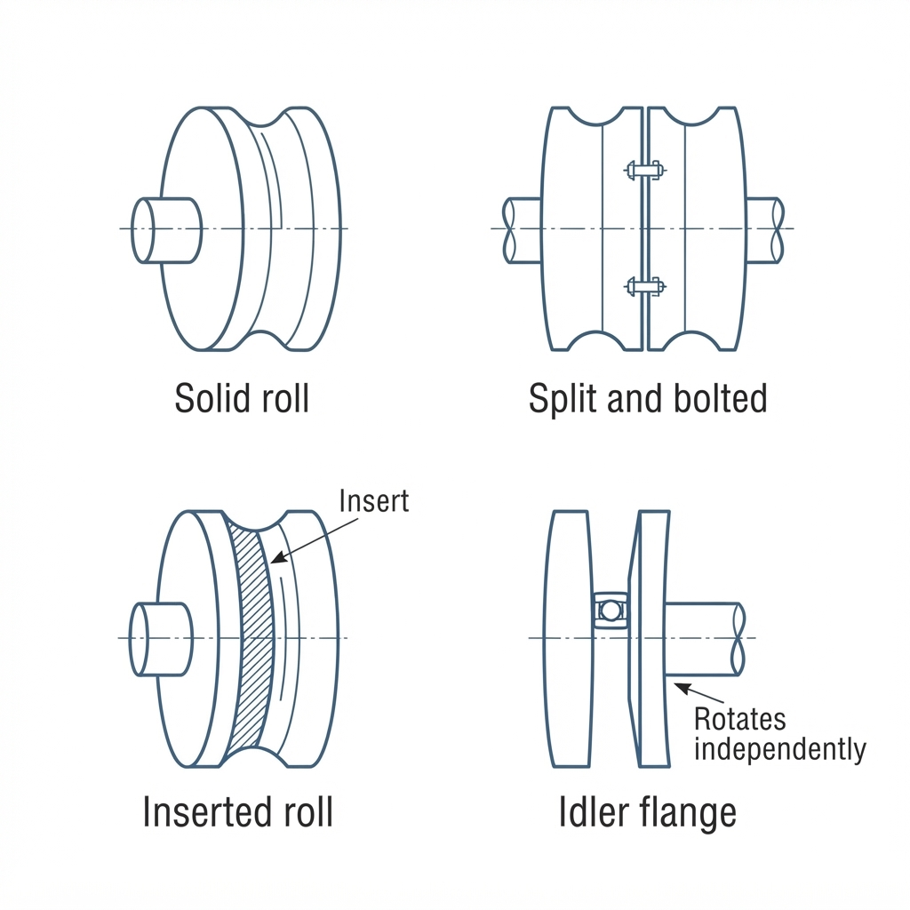
| Construction | Basic concept | Lifecycle implications |
|---|---|---|
| Solid roll | One-piece roll reconditioned by reducing diameter and restoring contour | Lower initial complexity; diameter and metal-line relationships change through regrind |
| Split-and-bolted roll | Segments are joined so mating faces can be reworked and working diameter restored | Can preserve working diameter; adds spacer, assembly, cost, and maintenance considerations |
| Inserted roll | High-wear region uses a replaceable material or segment | Targets wear cost; requires secure construction and blended working geometry |
| Idler or floating flange | A flange rotates independently to reduce surface-speed mismatch | Can reduce sliding/marking; adds bearings, parts, inspection, and maintenance |
These descriptions are general. The tooling designer and mill owner must confirm suitability for the actual load, speed, product, shaft, and maintenance environment.
Regrinding changes the setup state
For a solid driven roll, reducing the working diameter can change:
- Metal-line height
- Effective drive diameter
- Relationship to opposing and side rolls
- Roll-space and spacer requirements
- Section speed coordination
- Contact pressure and surface speed
- The setup chart used by production
| Quantity | Value (example) | Meaning |
|---|---|---|
| Original relevant diameter | 10.000 in | The reference diameter the setup chart was built around |
| Current diameter after regrinds | 9.900 in | The roll as it exists today |
| Diameter loss | 0.100 in | Original minus current |
| Center shift | 0.050 in | The roll centerline sits half the diameter loss lower |
| Candidate shim correction | 0.050 in | A geometric starting point for restoring the metal line |
This calculation is a geometric starting point, not authorization to shim a particular machine. Confirm the correct reference diameter, stand design, load path, OEM instructions, adjacent tooling, and plant procedure before use.
Inspect before, during, and after rework
Before rework
- Record tooling identity, station, drawing revision, and current dimensions
- Photograph and map wear, pickup, damage, or asymmetry
- Record the product symptoms and capability trend that triggered the decision
- Verify shafts, bores, faces, spacers, stands, and alignment so the tool is not blamed for a machine problem
- Define the restored contour and minimum remaining stock
At receipt from rework
- Verify identity and revision
- Compare inspection results with the approved rework drawing
- Confirm surface finish, contour, bore, faces, width, relevant diameters, and assembly
- Calculate required setup-document changes
- Quarantine mismatched or undocumented components
During tryout
- Use the revised setup record rather than the previous nominal chart
- Measure progressively through the line
- Compare product results, loads, marks, speed coordination, and stability
- Separate startup adjustments from the stable-running condition
After stable production
- Approve the new tooling state as a version
- Preserve the prior version and reason for change
- Update remaining-life and next-inspection decisions
- Link the tooling revision to affected products and setup records
Minimum tooling record
| Record group | Required information |
|---|---|
| Identity | Tooling set, individual roll, barcode/tag, mill, section, stand, orientation |
| Design | Drawing and revision, material, heat treatment, construction, nominal geometry |
| Current state | Actual dimensions, wear map, damage, pickup, surface, inspection date |
| Lifecycle | Manufacture, installation, footage/time if useful, removals, regrinds, replacements, modifications |
| Setup impact | Shims, spacers, side-roll height, metal line, speed/drive consideration, setup revision |
| Product evidence | Products run, material/gauge family, quality trend, marks, scrap, capability |
| Decision | Use, monitor, rework, repair, replace, or retire; approver and date |
Do not overwrite the original design with current dimensions. Both are required to understand what changed.
Rework based on capability, not calendar alone
Footage or time can support planning, but it is rarely sufficient by itself when the mill runs varied materials, gauges, finishes, and setups. A more useful decision combines:
- Contour and relevant diameter trend
- Bore, face, rim, and spacer condition
- Asymmetry or pickup
- Product dimension and surface capability
- Setup sensitivity and adjustment frequency
- Weld or forming evidence associated with the pass
- Expected rework stock
- Production and inventory risk
Set a local action point before the tooling can no longer make acceptable product. The threshold must be tied to the plant's measurement system, product requirements, tooling design, and validated experience.
Tooling and the digital thread
Tooling should link to the product and drawing revision, material family and qualified gauge range, mill and stand master data, setup revision, machine condition and alignment status, first-piece approval, quality and scrap records, maintenance work, and corrective action.
That relationship allows the plant to answer questions such as:
- Did the defect begin after a regrind or material change?
- Which products use the affected roll?
- Is one stand generating asymmetric wear across several sets?
- Did startup scrap increase after a spacer or shim revision?
- Does the last-good setup correspond to the current tooling geometry?
See the tube mill process control and digital setup records guide on this site for the broader data model.
Sources and technical scope
This guide synthesizes established tube-manufacturing principles, publicly available technical literature and practical industry review into an original, centralized reference. Its explanations, diagnostic frameworks, tables and illustrations were developed for this publication.
ASTM A513/A513M is the controlling specification for normative requirements. The current official standard, customer drawings, purchase documents and supplier agreements govern acceptance.
Purchase the current ASTM A513/A513M standard (opens the ASTM store in a new tab)